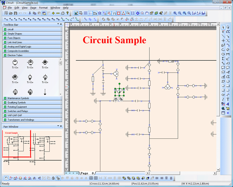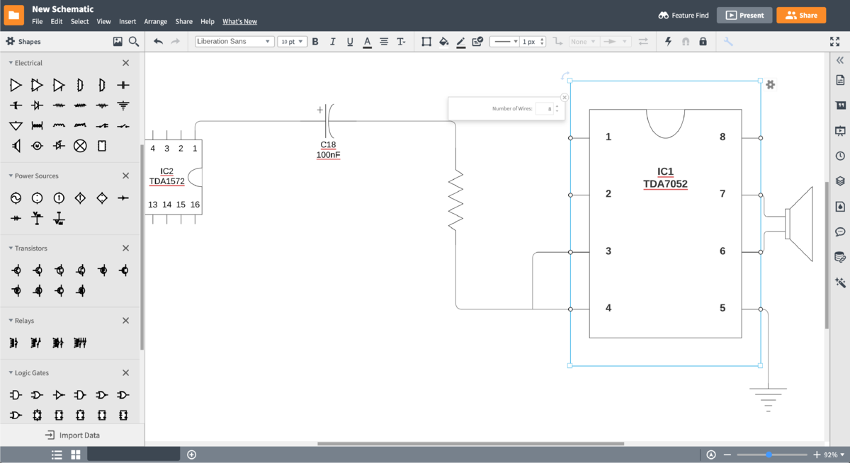

The leading EDA software vendors traditionally lack free versions, and professional licenses are unaffordable for amateurs. Open source hardware and easy-to-use development boards such as the Arduino and the Raspberry Pi have increased community interest in electronics, particularly in fablabs, hackerspaces and makerspaces. This popularity has been observed by Altium, and the most successful features of CircuitMaker 2000 have since been integrated in DXP 2004 and later were incorporated into Altium Designer. Due to its new status as abandonware, CircuitMaker 2000 remained popular among hobby users and students. When Protel was renamed Altium Limited in the early 2000s, engineering efforts were redirected towards the development of DXP 2004, and CircuitMaker 2000 was eventually discontinued. The wide availability of plug-ins and component libraries have accelerated adoption, and quickly amassed a worldwide community. Its ease of use and comparatively low cost quickly gained it popularity among students, and the software suite was commonly used to teach circuit board design to engineering students in universities. Protel CircuitMaker Įlectronic design automation software (EDA) developer Protel marketed CircuitMaker 2000 as a schematic capture tool, together with TraxMaker as its PCB layout counterpart, as a powerful yet affordable solution for circuit board needs.
ONLINE CIRCUIT MAKER PRO
CircuitMaker 5 for Windows 3.1, 9x and NT became available in 1997, CircuitMaker 6, CircuitMaker PRO, TraxMaker 3 and TraxMaker PRO in 1998. Other scenarios, the XOR behaves the same as the OR.History MicroCode CircuitMaker ĬircuitMaker, TraxMaker and SimCode were originally developed by the Orem-based MicroCode Engineering, Inc. However, with an XOR, (exclusive OR), if both inputs are 1, the output is 0. With an OR gate, if both inputs were 1, the output was 1. Just as the NAND gate could be thought of as an AND followed by a NOT, a NOR can be thought of as an OR also followed by a NOT. If neither input is 1, the output will be 0. If at least one of the inputs is 1, then the output will be 1. The OR gate has two inputs and one output. The symbol for NAND is the same as that for AND except for the addition of a small circle on the right side. The name NAND comes from joining NOT and AND. Its output is 0 when the two inputs are 1, and for all other cases, its output is 1. You can think of it as an AND gate followed immediately by a NOT gate. The NAND gate behaves in the opposite fashion to an AND gate.

The output is 1 if both inputs are 1, and for all other cases the output is 0. The AND gate has two inputs and one output. Tables listing all logical possibilities like this are known as truth tables.

The two possibilities are written out in the table below. The NOT gate is also known as an inverter because the output is the exact opposite of the input. Additionally, you can rename an output by double clicking on its label. If you need more space, click on the "Full screen mode" button which will increase the size of the workspace to fill the size of the window. Input (solid circle) and drag away and release, or alternatively you can right click anywhere on the connection. To remove connections, you can click on the To delete nodes, click the small cross in the top right corner of its enclosing box. You can drag it to your desired position. The new node will be placed in the top left hand corner, and To add a new logic gate, or an additional input or output block, choose from the dropdown menu and then click "add node". This is our way of differentiating between 0 (off) and 1 (on). Click the on/off switch and see what happens. Our "on/off" switch and "output block" aren't actually logic gates,īut they are required because they give us the 1s and 0s needed to see how the gates behave. On/off switch, and release the mouse when you are over the solid circle on the left side of the "output" block.įor each of the logic gates, outputs are hollow circles, and inputs are solid circles. To connect them, click and drag from the hollow circle on the right side of the

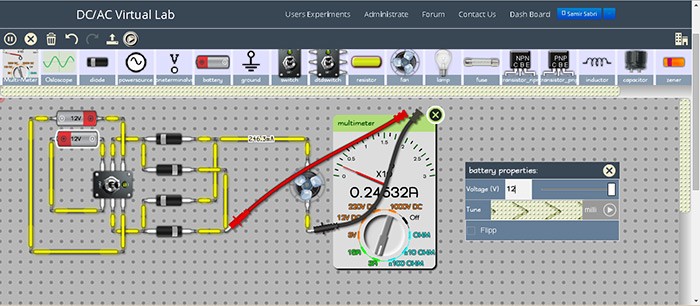
You are presented with a simple on/off input and an output. The demo above allows you to create sequences of logic gates to see how they behave when connected to various inputs and outputs.


 0 kommentar(er)
